Engineering Drawing
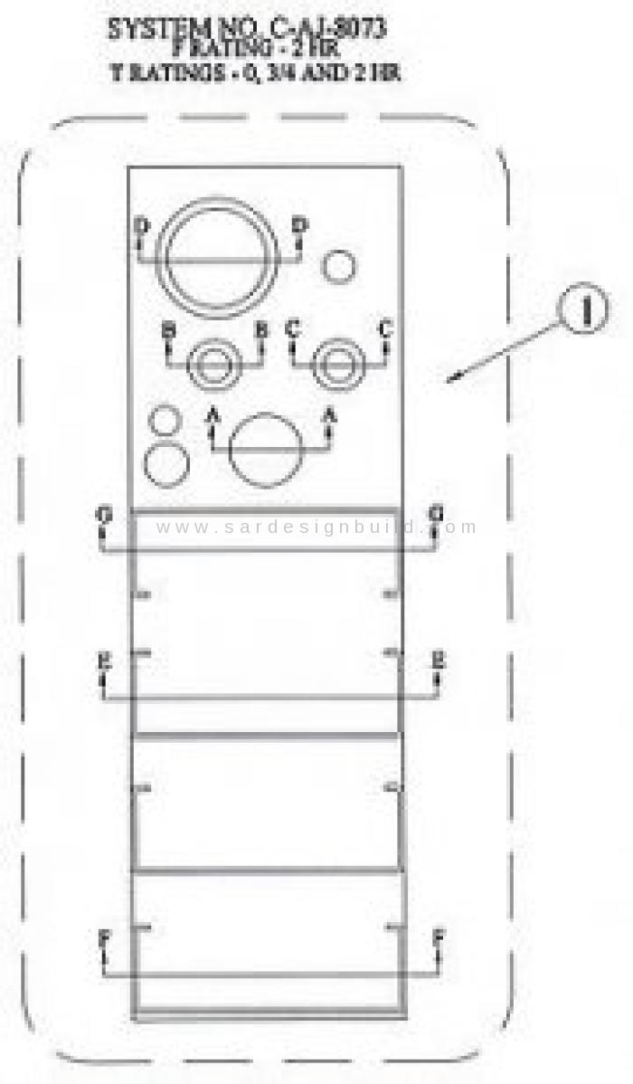
Technical drawing of a certification listing for a firestop system
An engineering drawing, a type of technical drawing, is created within the technical drawing discipline, and used to fully and clearly define requirements for engineered items.
Contents
Technical drawing of a certification listing for a firestop system
An engineering drawing, a type of technical drawing, is created within the technical drawing Technical drawing of a certification listing for a firestop system
1 Overview
2 Engineering drawings: common features
2.1 Line styles and types
2.2 Multiple views and projections
2.2.1 Orthographic projection
2.2.2 Auxiliary projection
2.2.3 Isometric projection
2.2.4 Oblique projection
2.2.5 Perspective
2.3 Scale
2.4 Showing dimensions
2.5 Sizes of drawings
2.6 Technical lettering
3 Example of an engineering drawing
Overview
Engineering drawings are usually created in accordance with standardized conventions for layout, nomenclature, interpretation, appearance (such as typefaces and line styles), size, etc. One such standardized convention is called GD&T.
The purpose of such a drawing is to accurately and unambiguously capture all the geometric features of a product or a component. The end goal of an engineering drawing is to convey all the required information that will allow a manufacturer to produce that component.
Engineering drawings used to be created by hand using tools such as pencils, ink, straightedges, T-squares, French curves, triangles, rulers, scales, and erasers. Today they are usually done electronically with computer-aided design (CAD).
The drawings are still often referred to as "blueprints" or "bluelines", although those terms are anachronistic from a literal perspective, since most copies of engineering drawings that were formerly made using a chemical-printing process that yielded graphics on blue-colored paper or, alternatively, of blue-lines on white paper, have been superseded by more modern reproduction processes that yield black or multicolour lines on white paper. The more generic term "print" is now in common usage in the U.S. to mean any paper copy of an engineering drawing.
The process of producing engineering drawings, and the skill of producing them, is often referred to as technical drawing or drafting, although technical drawings are also required for disciplines that would not ordinarily be thought of as parts of engineering.
Engineering drawings: common features
Drawings convey the following critical information:
- Geometry – the shape of the object; represented as views; how the object will look when it is viewed - from various standard directions, such as front, top, side, etc.
- Dimensions – the size of the object is captured in accepted units.
- tolerances – the allowable variations for each dimension.
- Material – represents what the item is made of.
- Finish – specifies the surface quality of the item, functional or cosmetic. For example, a mass-marketed product usually requires a much higher surface quality than, say, a component that goes inside industrial machinery.
[edit]Line styles and types
Standard engineering drawing line types Standard engineering drawing line types
A variety of line styles graphically represent physical objects. Types of lines include the following:
- visible ; are continuous lines used to depict edges directly visible from a particular angle.
- hidden ; are short-dashed lines that may be used to represent edges that are not directly visible.
- center ; are alternately long- and short-dashed lines that may be used to represent the axes of circular features.
- cutting plane ; are thin, medium-dashed lines, or thick alternately long- and double short-dashed that may be used to define sections for section views.
- section ; are thin lines in a pattern (pattern determined by the material being "cut" or "sectioned") used to indicate surfaces in section views resulting from "cutting." Section lines are commonly referred to as "cross-hatching."
Lines can also be classified by a letter classification in which each line is given a letter.
- Type A lines show the outline of the feature of an object. They are the thickest lines on a drawing and done with a pencil softer than HB.
- Type B lines are dimension lines and are used for dimensioning, projecting, extending, or leaders. A harder pencil should be used, such as a 2H.
- Type C lines are used for breaks when the whole object is not shown. They are freehand drawn and only for short breaks. 2H pencil
- Type D lines are similar to Type C, except they are zigzagged and only for longer breaks. 2H pencil
- Type E lines indicate hidden outlines of internal features of an object. They are dotted lines. 2H pencil
- Type F lines are Type F[typo] lines, except they are used for drawings in electrotechnology. 2H pencil
- Type G lines are used for centre lines. They are dotted lines, but a long line of 10–20 mm, then a gap, then a small line of 2 mm. 2H pencil
- Type H lines are the same as Type G, except that every second long line is thicker. They indicate the cutting plane of an object. 2H pencil
- Type K lines indicate the alternate positions of an object and the line taken by that object. They are drawn with a long line of 10–20 mm, then a small gap, then a small line of 2 mm, then a gap, then another small line. 2H pencil.
Multiple views and projections
In most cases, a single view is not sufficient to show all necessary features, and several views are used. Types of views include the following: Image of a part represented in First Angle Projection
 Symbols used to define whether a projection is either Third Angle (right) or First Angle (left).
 Isometric view of the object shown in the engineering drawing further down the page.Orthographic projection
The orthographic projection shows the object as it looks from the front, right, left, top, bottom, or back, and are typically positioned relative to each other according to the rules of either first-angle or third-angle projection.
- First angle projection is the ISO standard and is primarily used in Europe. The 3D object is projected into 2D "paper" space as if you were looking at an X-ray of the object: the top view is under the front view, the right view is at the left of the front view.
- Third angle projection is primarily used in the United States and Canada, where it is the default projection system according to BS 8888:2006, the left view is placed on the left and the top view on the top.
Not all views are necessarily used, and determination of what surface constitutes the front, back, top and bottom varies depending on the projection used.
Auxiliary projection
An auxiliary view is an orthographic view that is projected into any plane other than one of the six principal views.[1] These views are typically used when an object contains some sort of inclined plane. Using the auxiliary view allows for that inclined plane (and any other significant features) to be projected in their true size and shape. The true size and shape of any feature in an engineering drawing can only be known when the Line of Sight (LOS) is perpendicular to the plane being referenced.
Isometric projection
The isometric projection show the object from angles in which the scales along each axis of the object are equal. Isometric projection corresponds to rotation of the object by ± 45° about the vertical axis, followed by rotation of approximately ± 35.264° [= arcsin(tan(30°))] about the horizontal axis starting from an orthographic projection view. "Isometric" comes from the Greek for "same measure." One of the things that makes isometric drawings so attractive is the ease with which 60 degree angles can be constructed with only a compass and straightedge.
Isometric projection is a type of axonometric projection. The other two types of axonometric projection are:
- Dimetric projection
- Trimetric projection
Oblique projection
An oblique projection is a simple type of graphical projection used for producing pictorial, two-dimensional images of three-dimensional objects:
- it projects an image by intersecting parallel rays (projectors)
- from the three-dimensional source object with the drawing surface (projection plan).
In both oblique projection and orthographic projection, parallel lines of the source object produce parallel lines in the projected image.
Perspective
Perspective is an approximate representation on a flat surface, of an image as it is perceived by the eye. The two most characteristic features of perspective are that objects are drawn:
- Smaller as their distance from the observer increases
- Foreshortened: the size of an object's dimensions along the line of sight are relatively shorter than dimensions across the line of sight.
Scale
Main articles: Architect's scale and Engineer's scale
Plans are usually "scale drawings", meaning that the plans are drawn at specific ratio relative to the actual size of the place or object. Various scales may be used for different drawings in a set. For example, a floor plan may be drawn at 1:50 (or 1/4"=1'-0") whereas a detailed view may be drawn at 1:25 (or 1/2"=1'-0"). Site plans are often drawn at 1:200 or 1:100.
Showing dimensions
The required sizes of features are conveyed through use of dimensions. Distances may be indicated with either of two standardized forms of dimension: linear and ordinate.
- With linear dimensions, two parallel lines, called "extension lines," spaced at the distance between two features, are shown at each of the features. A line perpendicular to the extension lines, called a "dimension line," with arrows at its endpoints, is shown between, and terminating at, the extension lines. The distance is indicated numerically at the midpoint of the dimension line, either adjacent to it, or in a gap provided for it.
- With ordinate dimensions, one horizontal and one vertical extension line establish an origin for the entire view. The origin is identified with zeroes placed at the ends of these extension lines. Distances along the x- and y-axes to other features are specified using other extension lines, with the distances indicated numerically at their ends.
Sizes of circular features are indicated using either diametral or radial dimensions. Radial dimensions use an "R" followed by the value for the radius; Diametral dimensions use a circle with forward-leaning diagonal line through it, called the diameter symbol, followed by the value for the diameter. A radially-aligned line with arrowhead pointing to the circular feature, called a leader, is used in conjunction with both diametral and radial dimensions. All types of dimensions are typically composed of two parts: the nominal value, which is the "ideal" size of the feature, and the tolerance, which specifies the amount that the value may vary above and below the nominal.
- Geometric dimensioning and tolerancing is a method of specifying the functional geometry of an object.
Sizes of drawings
Main article: Paper size
Sizes of drawings typically comply with either of two different standards, ISO (World Standard) or U.S. customary, according to the following tables: ISO paper sizesISO paper sizes
ISO A Drawing Sizes (mm)
A4 210 X 297
A3 297 X 420
A2 420 X 594
A1 594 X 841
A0 841 X 1189
U.S. Customary Drawing Sizes
A 8.5" X 11"
B 11" X 17"
C 17" X 22"
D 22" X 34"
E 34" X 44"
Other U.S. Drawing Sizes
D1 24" X 36"
E1 30" X 42"
The metric drawing sizes correspond to international paper sizes. These developed further refinements in the second half of the twentieth century, when photocopying became cheap. Engineering drawings could be readily doubled (or halved) in size and put on the next larger (or, respectively, smaller) size of paper with no waste of space. And the metric technical pens were chosen in sizes so that one could add detail or drafting changes with a pen width changing by approximately a factor of the square root of 2. A full set of pens would have the following nib sizes: 0.13, 0.18, 0.25, 0.35, 0.5, 0.7, 1.0, 1.5, and 2.0 mm. However, the International Organization for Standardization (ISO) called for four pen widths and set a colour code for each: 0.25 (white), 0.35 (yellow), 0.5 (brown), 0.7 (blue); these nibs produced lines that related to various text character heights and the ISO paper sizes.
All ISO paper sizes have the same aspect ratio, one to the square root of 2, meaning that a document designed for any given size can be enlarged or reduced to any other size and will fit perfectly. Given this ease of changing sizes, it is of course common to copy or print a given document on different sizes of paper, especially within a series, e.g. a drawing on A3 may be enlarged to A2 or reduced to A4.
The U.S. customary "A-size" corresponds to "letter" size, and "B-size" corresponds to "ledger" or "tabloid" size. There were also once British paper sizes, which went by names rather than alphanumeric designations.
American National Standards Institute (ANSI) Y14.2, Y14.3, and Y14.5 are standards that are commonly used in the U.S.
Technical lettering
Technical lettering is the process of forming letters, numerals, and other characters in technical drawing. It is used to describe, or provide detailed specifications for, an object. With the goals of legibility and uniformity, styles are standardized and lettering ability has little relationship to normal writing ability. Engineering drawings use a Gothic sans-serif script, formed by a series of short strokes. Lower case letters are rare in most drawings of machines.
Example of an engineering drawing
Example mechanical drawing
Here is an example of an engineering drawing (an isometric view of the same object is shown above). The different line types are colored for clarity.
- Black = object line and hatching
- Red = hidden line
- Blue = center line of piece or opening
- Magenta = phantom line or cutting plane line
kembali ke halaman:
S A R Office
Jl. Anggrek Raya Blok E No. 36-37, RT. 002/019, Taman Setia Mekar, Tambun Selatan Bekasi 17510
Phone: +62 21 8835 8846
WA: +62 8778 1853 073
Email: sardesignbuild@yahoo.com
Kirim Pertanyaan Anda disini :